Hardware startup companies often validate their makers’ project using desktop 3D printers based on 3D-printable models; however, converting such prototypes into metal functional parts for small-scale production can result in price quotation increases by 30% to 45% and several weeks of wait. While additive manufacturing creates deep undercuts and angular holes in layers, traditional machining needs many fixture changes to achieve multi-face tools. The guide is intended to explain the process of applying multi-axis kinematics to combine additive design files with precision manufacturing from the mechanical limitations of traditional toolpathing perspective.
Why Do 3D Printable CAD Design Files Fail During Conventional 3-Axis Metal Machining?
Both the desktop FDM and SLA printers construct parts progressively with almost infinite geometric flexibility, while the conventional 3-axis milling machines have very restrictive tool access confined to the vertical Z-axis only:
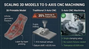
- Datum Shift Accumulation: Original CAD files need between four and six clampings on the 3-axis machine, introducing positional errors exceeding ±0.05 mm.
- Expensive Fixtures: The angled surfaces and compound parts necessitate the use of customized soft jaws or multi-angle fixtures, adding to the non-recurring engineering (NRE) costs.
- Hard-to-Reach Holes: Undercuts and cross holes made with soluble supports are hard to reach by any rigid end mill mounted vertically.
According to ASME Y14.5-2018 tolerancing theory and the NIST Smart Manufacturing Operations Planning and Control system, reducing the number of datum transfers is crucial in maintaining positional accuracy.
Figure 1: Kinematic and cost comparison when scaling complex 3D printable models from multi-setup 3-axis milling (>±0.05 mm datum shift) to single-setup 5-axis CNC machining (±0.005 mm tolerance).
How Does 5-Axis CNC Work to Eliminate Multi-Setup Errors on Complex Geometry?
In order to solve the problems arising from one-directional line-of-sight limitation, multi-axis machining centers provide an extra pair of rotating degrees of freedom (usually A and B or A and C axis) in addition to the usual X, Y, and Z axis movements. Such movement possibilities allow the cutting tool or part to rotate and achieve five sides of the part while it is fixtured once.
3+2 Positioning Compared to Simultaneous 5-Axis Machining
In 3+2 positioning, the rotation axes position the workpiece at a certain angle, which is constant throughout the entire process of cutting on three axes. It performs very well in cutting angled mounting surfaces, drilling holes on oblique angles, and cutting pockets with short rigid tools resistant to bending. On the other hand, in simultaneous 5-axis CNC machining, all five axes rotate simultaneously and keep a constant chip load and tool engagement angle.
Shorter Reach of Cutting Tool and Chatter Control
By tilting the workpiece with respect to the spindle, machinists have the advantage of using shorter end mills with lower aspect ratios. Tool overhang reduction significantly mitigates vibration-related chatter, thus ensuring better surface quality up to Ra 0.8 μm while maintaining micron-level dimensional precision. For engineers in the hardware community that assess multi-axis kinematics for consolidation of setup processes on complex housings, this full-fledged engineering analysis of 5-axis CNC milling explains the essential mechanics involved.
Which Types of 5-Axis CNC Machines Best Fit Different Functional Parts and Materials?
Selecting the appropriate machine architecture ensures optimal rigidity, work-envelope clearance, and cycle-time efficiency when scaling functional parts from polymer prototypes to aerospace or medical alloys.
| Machine Architecture | Rotary Axis Configuration | Optimal Part Envelope | Ideal Materials & Industrial Applications |
| Trunnion-Style (Table-Table) | A-axis and C-axis integrated into the worktable | Small to medium (< 500 mm) | AL 7075-T651, Titanium Ti-6Al-4V; medical implants, optical mounts, precision drone frames |
| Swivel-Head (Head-Table) | B-axis tilting spindle head + C-axis rotary table | Medium to large (500–1,200 mm) | Stainless Steel 316L, Inconel; automotive powertrain housings, robotics joints |
| Gantry / Double-Pivot (Head-Head) | A-axis and B/C-axis mounted directly on the spindle head | Extra-large (> 1,200 mm) | Carbon fiber composites, Aluminum 6061; aerospace structural ribs, large molds |
What Are the Measurable Advantages of 5-Axis Machining Over 3-Axis in Low-Volume Production?
Moving from rapid prototype units to low-volume production lots in the range of 50 to 500 units per lot will see a paradigm shift towards multi-axis processing of parts.
- No Setup Cost for Multi-Angle Fixtures: The removal of any need for multi-angle fixtures reduces up-front cost and cuts down setup time by 40%-60%, enabling rapid iteration without tying up money in tooling.
- Complete Features in Single Setup: Ensuring that all key features are completed in a single clamping ensures coaxiality and positional accuracy to ±0.005 mm, tested against Zeiss CMM calibration standards (MPEE ≤ 0.0009 mm).
- Longer Tool Lifespan and Higher Feeding Speeds: Angling ball nose end mills avoids cutting at the zero velocity point on the tool tip, ensuring higher surface speed (Vc=250 m/min in aluminum) which results in longer life for the cutters.
As reported in the SME manufacturing engineering machining knowledge base and the Haizol 2026 China Precision CNC Tiers pricing white paper, multi-axis operations always result in lower landed cost of parts with complex geometry.
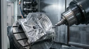
Figure 2: Single-setup 5-axis CNC machining of a multi-pocket aluminum housing, eliminating custom multi-angle fixtures and maintaining micron-level surface integrity during low-volume production.
How Can Engineers Optimize 3D CAD Models for Complex Part Machining with 5-Axis Before Quoting?
Export of clean B-REP files (STEP or IGES) instead of STL mesh, followed by design improvements to achieve optimal DFM before RFQ submission is necessary:
- Specify Internal Fillet Radii: Provide a minimum internal fillet radius of no less than 1/6 of the pocket depth to allow use of the standard cylindrical cutters to produce the required part geometry.
- Specify Proper Aspect Ratios for Holes and Slots: Make sure that the aspect ratio of deep holes and narrow slots does not exceed 6:1 to avoid tool deflections in machining.
- Provide Proper Wall Thickness: Maintain a wall thickness of 0.8 mm for aluminum and 1.0 mm for stainless steel and titanium to avoid any warping due to residual stresses.
- Provide Selective Tolerancing: Tight tolerances of ±0.01 mm must be specified only for bearing bores and datum surfaces, while other surfaces should be specified according to ISO 2768-M standard.
Conclusion
From developing 3D printable desktop models to producing highly reliable metal parts, scaling hardware involves synchronizing the geometric intent with the kinematics of subtractive manufacturing. With an appreciation of how does 5 axis CNC work, the selection of the appropriate machine configuration, and DFM principles applied during CAD modeling, engineering teams will ensure no datum errors in multi-setup processes, lower costs of tooling, and fast low-volume production.
FAQs
Q1: Can STL file models downloaded from the 3D printing library be used directly for 5-axis CNC machining?
A1: No. These are triangulated surfaces without exact dimensions. Engineers have to translate the designs to B-Rep solid modeling format like STEP or IGES to define exact tolerances and toolpath.
Q2: When does 5-axis CNC machining become less costly compared to 3-axis machining in prototyping?
A2: When a part requires three or more clamping setups on a 3-axis mill, 5-axis machining becomes more cost-effective by eliminating custom fixtures, reducing labor hours, and preventing datum shift scrap.
Q3: In what way does 3+2 machining differ from simultaneous 5-axis machining?
A3: 3+2 machining fixes the two rotary axes in their respective positions prior to cutting a flat and tilted surface, while simultaneous 5-axis machining uses all five axes in continuous motion to create smooth organic shapes.
Q4: What are the tolerance capabilities of an industrial 5-axis CNC machine?
A4: Tolerances of ±0.005 mm to ±0.01 mm per setup can easily be maintained using industrial 5-axis CNC machines while ensuring coaxial and profiling accuracy as validated by CMM.
Q5: What are some of the most common materials used in machining scaled-up versions of 3D printed prototypes?
A5: Aluminum 6061-T6 and 7075-T651 are some of the most preferred metals in making lightweight enclosures, while Stainless Steel 304/316L, Titanium Ti-6Al-4V, and Brass C36000 are chosen for high stress and medical uses.
Author Bio
Written by the Senior Mechanical Engineering Group at LS Manufacturing, a contract manufacturer that aids hardware engineers with scaling their designs from rapid prototypes to metal fabrication. Running on ISO 9001, IATF 16949, ISO 14001, AS9100D, and ISO 13485 quality management standards, the group provides micron tolerances and full DFM assessment. Engineers who want to translate their 3D CAD designs into metal components can simply upload STEP files to the official website to receive free DFM assessment and quote.